
Microchamber design and development
As part of the project’s initial phase, we successfully redesigned and developed the microchamber for Raman backscattering experiments. The goal was to improve the experimental setup by incorporating specific optical and optomechanical components.
The components in the microchamber are essential for inelastic light scattering experiments, particularly in backscattering geometry. This specially designed configuration overcomes the limitations of commercially available setups, allowing access to low-intensity excitations that reveal valuable, often elusive, information about underlying physical processes.
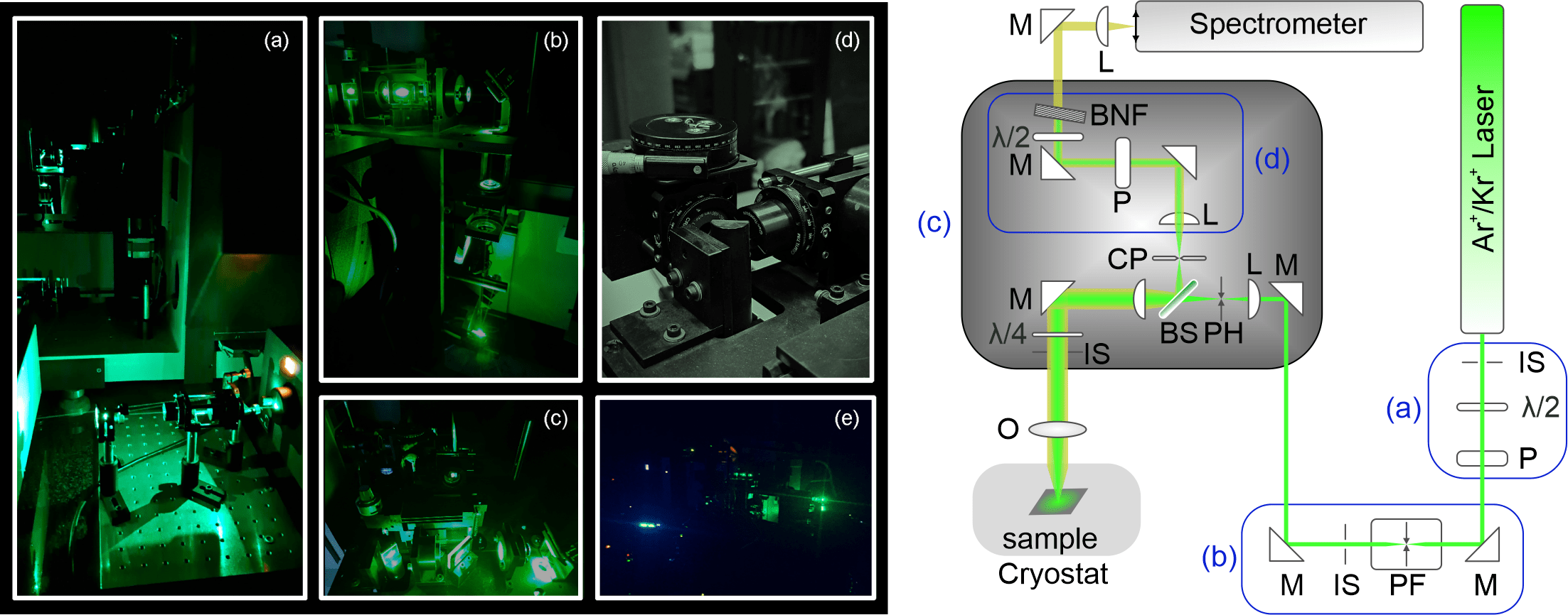
To achieve the project’s objectives, we developed a new light scattering experiment by integrating existing equipment with newly acquired optical and optomechanical components. This redesigned setup, illustrated in the figure, offers improved resolution and transmittance trough spectrometer, effective suppression of elastically scattered and stray light, and precise control over polarization (both linear and circular).
Redesigned and reconstructed optical path and microchamber. On the left panel, real photos of the setup components are displayed. Specifically, (a) shows the polarizer and quarter-waveplate, which control incoming light power and polarization, (b) depicts the entrance path to the microchamber containing mirrors and plasma filters, (c) shows the microchamber with its internal elements, (d) illustrates the optical elements before the scattered light enters the spectrometer, and (e) displays the working environment. On the right panel, a schematic representation of the elements shown in the left panel is provided. The optical and optomechanical components are labeled as follows: λ/2 – half-waveplate, IS – iris, P – Glan Thompson polarizer, M – mirrors, PF – plasma filter, L – lens, PH – pinhole, BS – beam splitter, λ/4 – quarter-waveplate, O – objective, CP – confocal pinhole, BNF – Bragg notch filter.
Key Components of the Redesigned Microchamber
Polarization and Power Control: The polarization and power of the incident light are precisely controlled using a combination of a half-wave plate and a Glan-Thompson polarizer. This setup allows fine-tuned adjustments to the light’s characteristics before it enters the system.
Quarter-Wave Plate: A quarter-wave plate is strategically positioned at the entrance to the microscope. The angle of the quarter-wave plate determines the polarization state of the incident and scattered photons. For example, when the plate is set to 0°, linear polarization is maintained. Adjusting the angle to +45° or -45° results in circular polarization, producing either right-handed (RR) or left-handed (RL) circular polarization.
Entrance to the Spectrometer: Along the optical path to the spectrometer, a polarizer and a half-wave plate are set to maximize the transmission of scattered light through the spectrometer. Just before entering the spectrometer, a notch filter is employed to eliminate elastically scattered light.
The completion of Activity 1.1 marks the first deliverable and milestone of the project, setting a solid foundation for the subsequent phases and ensuring that our laboratory is equipped to undertake complex Raman experiments in backscattering configuration.
Inelastic light scattering setup in backscattering configuration

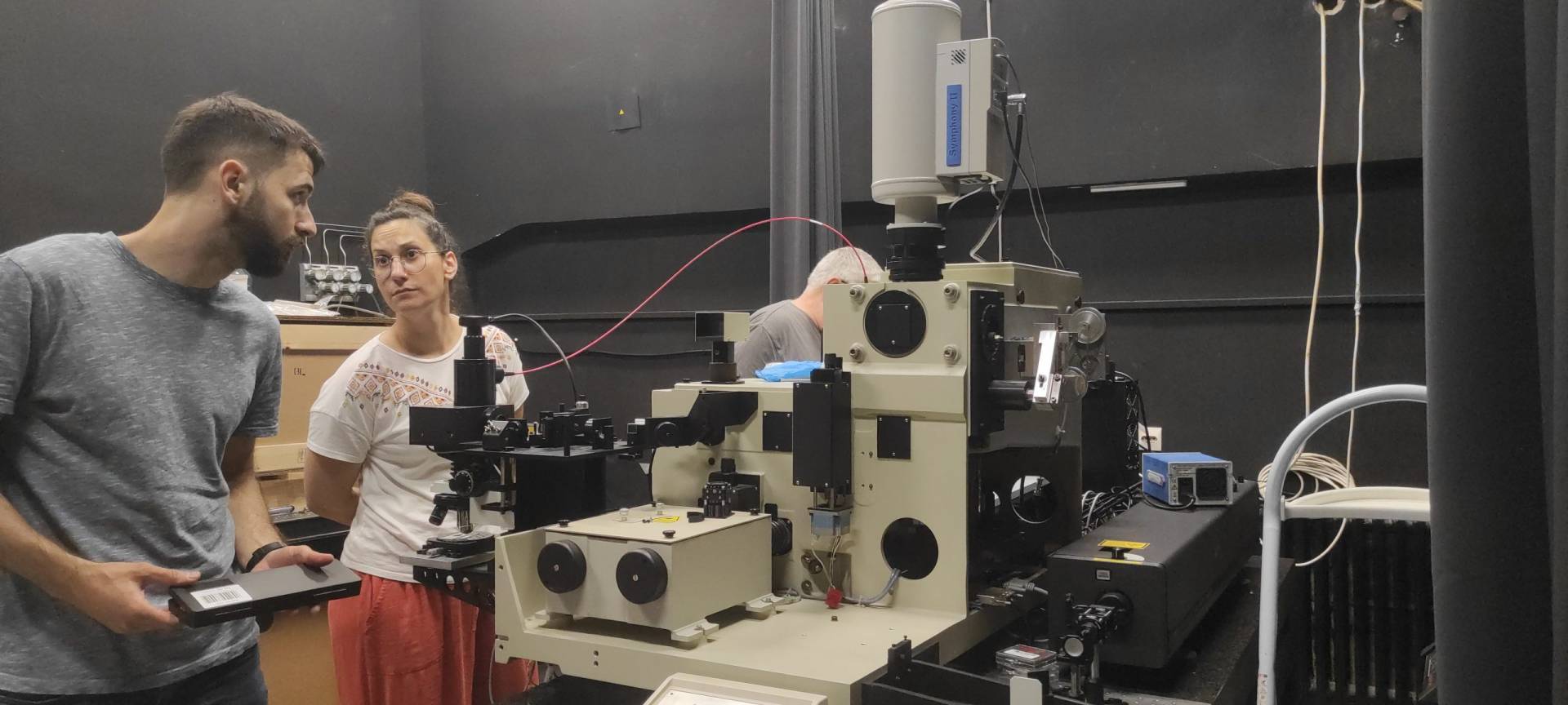
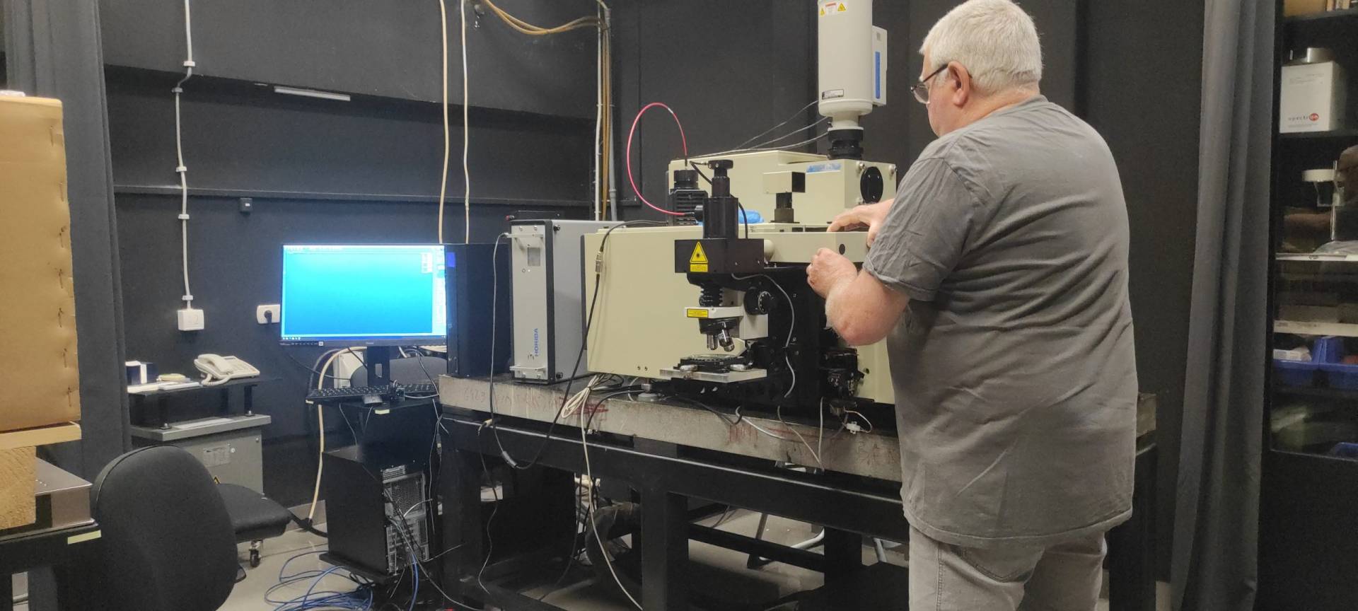
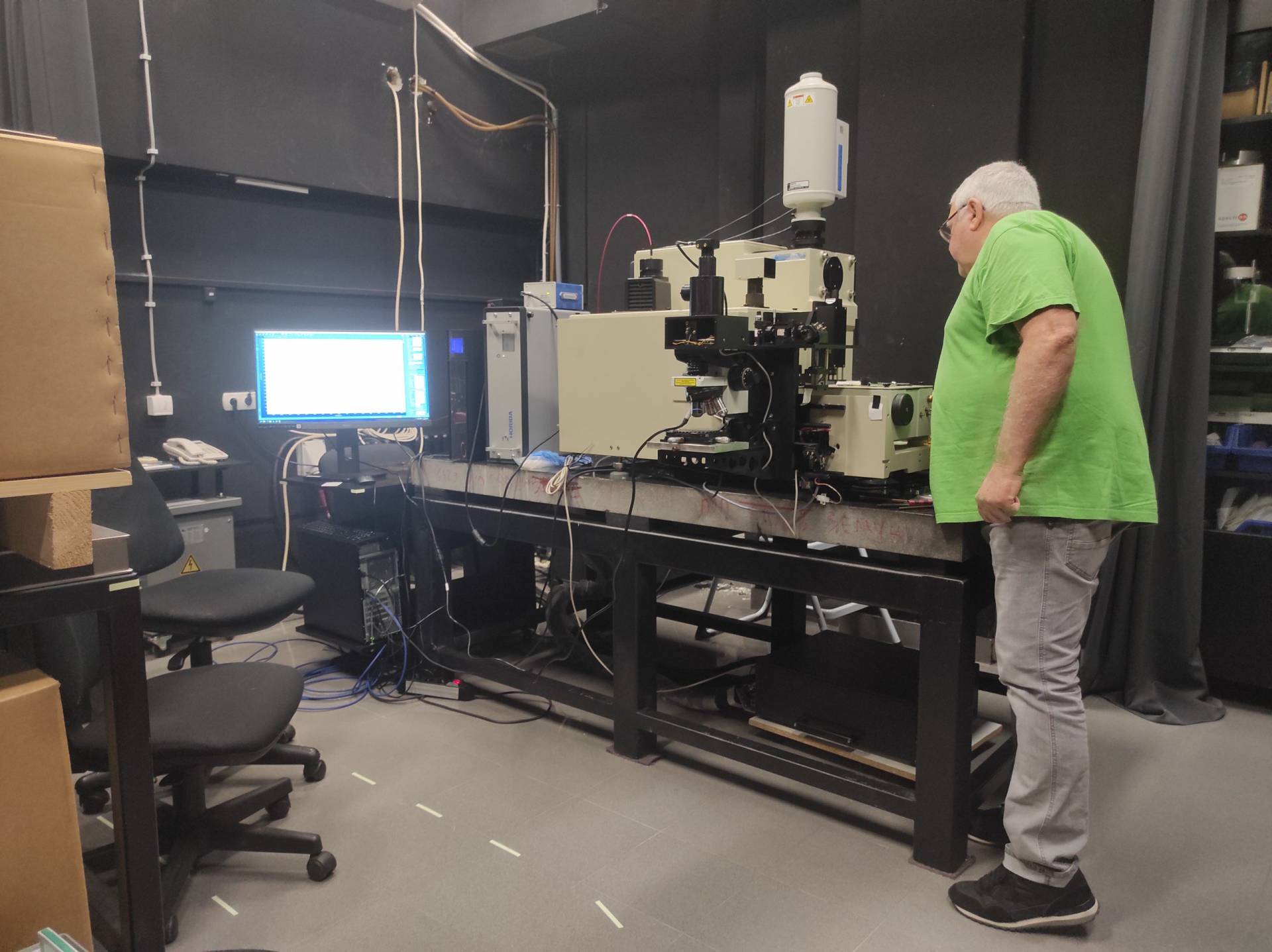
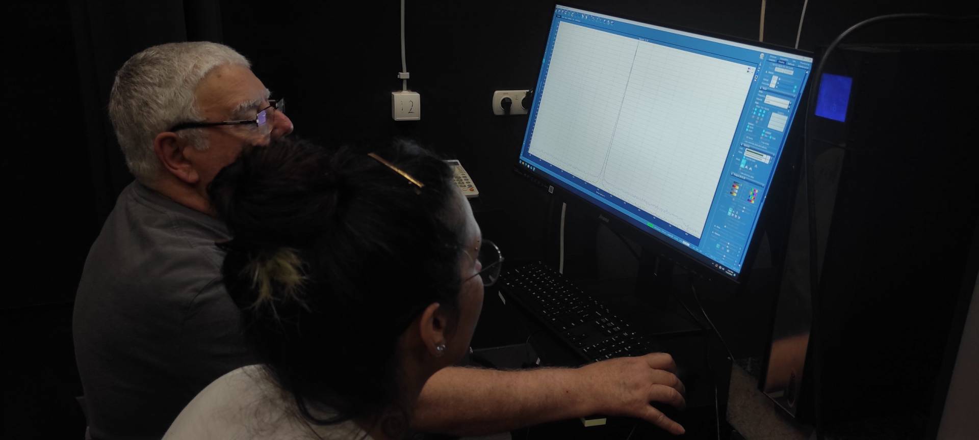
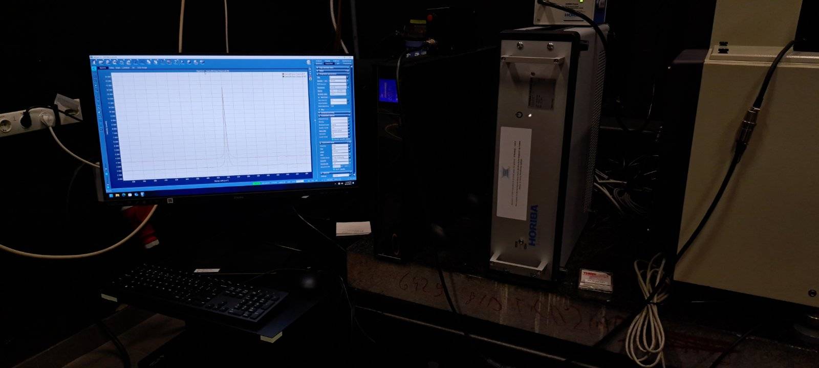
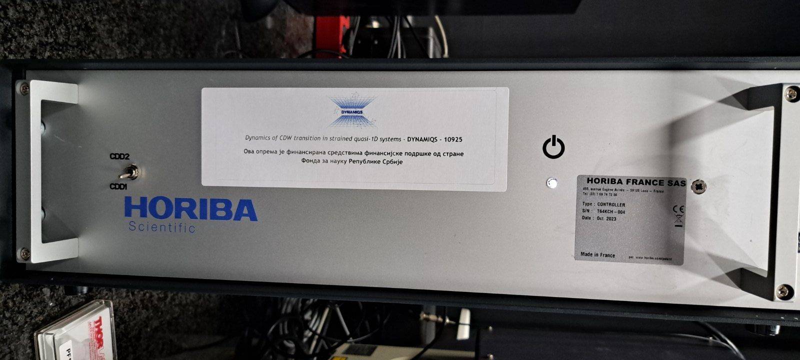


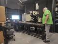

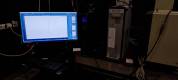
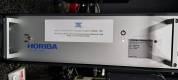


The second key activity in the Project’s initial phase involved the integration of the new S3000 controller for the T64000 Raman system, along with its setup, initialization, and optimization. The controller manages the Raman system through communication with the newly upgraded software, the latest version of the LabSpec6 (Horiba Scientific), which offers complete functionality for acquisition, processing, analysis, and data display. This latest software version enables remote operation of all Raman system components and provides a higher level of functionality with improved ease of use compared to its predecessor.
As a result, system performance has been maximized, allowing for advanced experimental capabilities and ensuring optimal performance, enabling us to conduct future experiments using the most advanced, state-of-the-art technologies available. These were critical steps to enhance our experimental capabilities and ensure the optimal performance in the future experiments as part of the broader project objectives.


Moreover, the T64000 Raman system was improved with implementing new electronic components, including the upgraded optical camera for the microscope. These installations were carried out by a Horiba service engineer, ensuring precision, reliability, and effectiveness in the upgrade process.
This extensive upgrade has positioned our laboratory to conduct cutting-edge research, laying the foundation for significant advancements in experimental outcomes. The completion of Activity 1.2 marks the second project deliverable, establishing a solid base for subsequent phases and ensuring that our laboratory is fully equipped to perform complex Raman experiments in backscattering configuration.
Running commercial strain cell
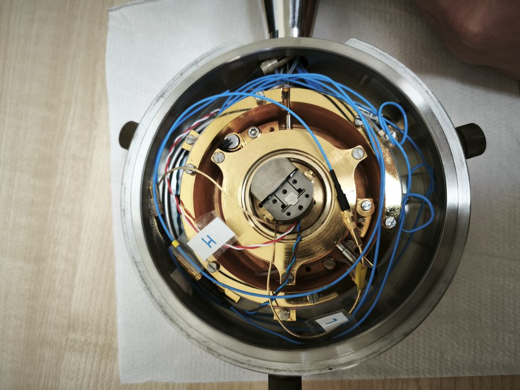
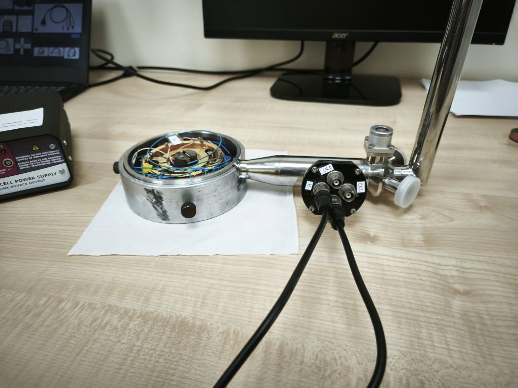
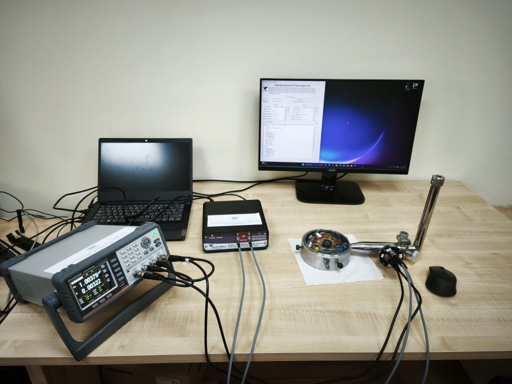
After successfully completing the first two key activities for our project it was time for our third project phase; to install and optimize the commercial strain cell and have it running for the experiments we have planned in the next months. The complete strain setup for our cryostat consists of three devices; Razorbill Instruments SC100 strain cell, RP100 Power Supply and precision LCR meter.
Although a commercially available strain cell enhances our setup’s reliability and capabilities, several issues needed resolution before we could begin using it effectively. Each of the three devices required specific configurations to integrate seamlessly into our system, as they needed to be properly set up and calibrated to function correctly. To incorporate the strain cell into the CryoVac Konti He-flow cryostat, we designed a special adapter, ensuring an integration into our existing setup.
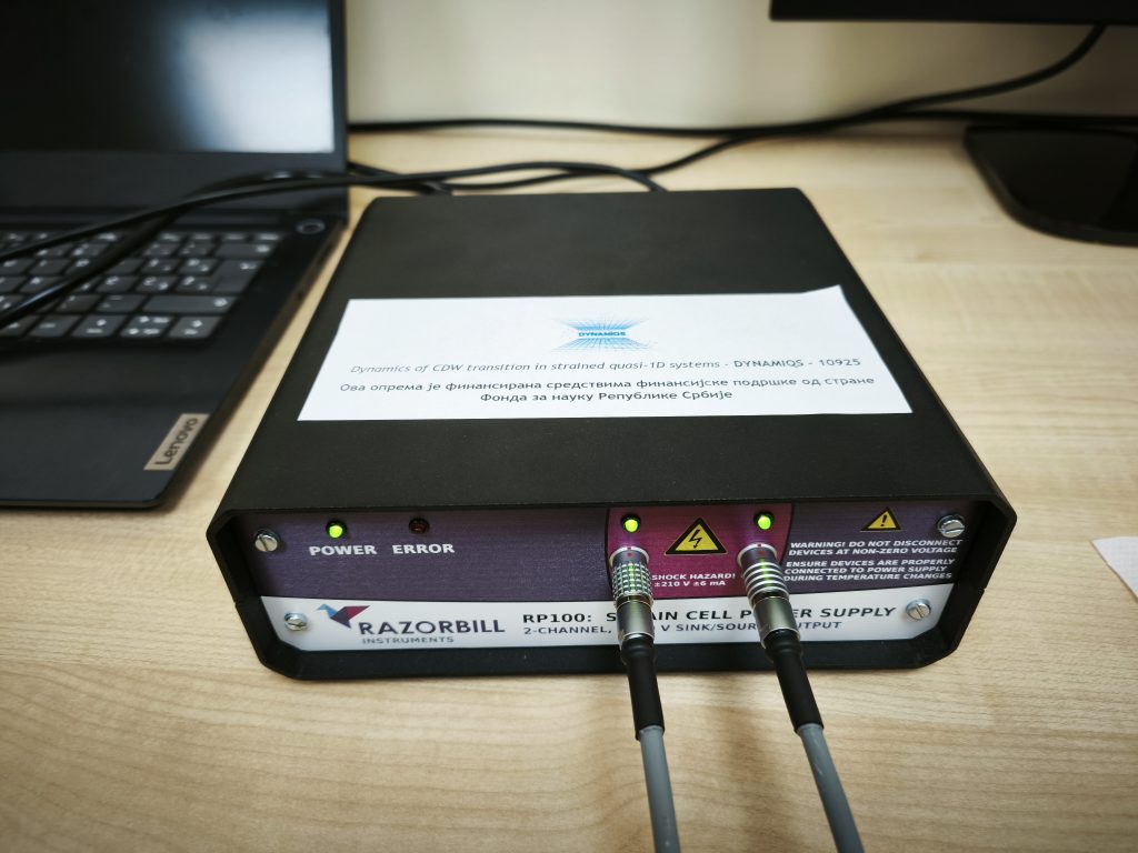
The Razorbill RP100 power supply is designed to connect directly to the strain cell. However, since our experiments involve low temperatures, additional setup was required to ensure compatibility. Proper configuration was crucial to prevent potential damage to the strain cell. After making the necessary adjustments, we confirmed that the power supply was functioning correctly with both the strain cell and cryostat setup.
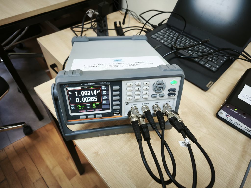
The LCR6300 required an adjustment to function with our strain cell. By using BNC Tee connectors, we successfully established a working connection, allowing the LCR meter to measure effectively. Despite measuring from the connection point rather than the cell, the setup proved reliable due to negligible impedance differences.
After completing the hardware setup, we installed the necessary software, calibrated the system, and conducted initial tests using a dummy sample. These steps ensured that the strain cell was functioning correctly and ready for future experiments.
This marks the successful completion of Activity 3: Implementation of the Commercial Strain Cell, a crucial milestone in Work Package 1: Design and Development of Experimental Setup. With all essential equipment now fully installed and operational, we have successfully achieved Deliverable 1.3: Running Commercial Strain Cell and Milestone 1.2: Operational Strain Cell.